Plumbing is as follows:
Whipple->tank->pump->chiller->Whipple
My opinion, and the way my plumbing is; Hot from SC to pump, pump to chiller, chiller to tank, tank to SC, repeat. My tank also is not just a tank, it’s baffled like a 4 pass shell and tube heat exchanger is. ie a 18” long 4”x4” tank is baffled into 4 1” square sections which are configured so from entry to exit is 4 1” square paths times 18” long each for an effective cold water column that is 64” long, add that to 36” of tube from chiller to tank and say 48” tank to SC inlet give a about 136” column of chilled water before the hot stuff starts to mix back into the mix. I get a 1/3rd to 1/2 mile run completed before I see a rise in chilled water temp at SC inlet.
I have been around large industrial chilled water systems for 25+ years, systems with 2400 tons of capacity with 200 hp circulation pumps. Hot water comes out of hot side of process return tank and goes to the chiller, returns from chiller and to the process. The mixing of hot water in the supply tank helps to prevent large temperature fluctuations to the inlet of the chillers which keeps expansion valves from hunting all over causing pressure fluctuations in the refrigerant system. The out let from the chillers feeding directly to the process then makes a huge column of stable temperature water which keeps process variations down. I modeled my system after this.
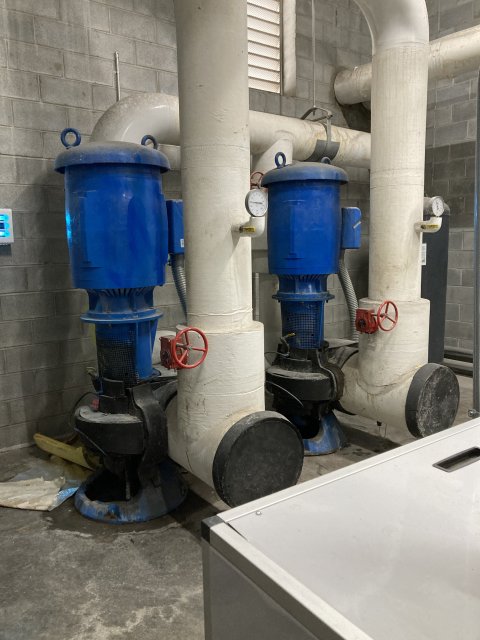
Here’s a portion of that chilled water system.
@Hickster no playing with yourself with these pictures lol get a Playboy for that 😂


